|
|
|
Go to our new Web site www.sciensoria.fr ![]()
Click on each piece of the puzzle to find out the technologies we can offer
THICKNESS MEASUREMENT return home ![]() Top of page
Top of page
Measurement of plates thickness
Measurement of tube thickness
Sciensoria has invented an unique solution for measuring the thickness of conductive materials. With a probe applied to a single side of the target, without mechanical contact, the instrument indicates the thickness under the probe. The target can be flat or curved, a large range of conductive materials are accepted (except magnetic materials which require more complex setup). The system does not require complex calibration procedure on standards, so easier to use than many other commercial systems.
Advantages of our technique:
Single-sided measurement, no mechanical contact
Good tolerance with respect to lift-off and tilt
Stable with respect to materials changes (automatic compensation of conductivity, permeability and lift-off).
Small measurement spot
Wide measurement range
Measurement wall thickness of tubes, tank, closed products, no calibration required
View our demo video of a thickness measurement with the Conducsens/TK-Sens(tm) system
View the video in French version
Measurement of thickness in additive manufacturing return home
Top of page
The additive manufacturing is a new application field of the multi-frequency eddy current testing method.
Share this page
Measurement of thin sheet thickness return home
For thickness measurement, the eddy current method is an ideal complement to the ultrasound method. In effect, while ultrasound method work well on great thickness values but fail on very small thickness values, inversely, eddy current method work very well on thin layers.
As thickness increases, the sensitivity of eddy current measurement decreases, as a consequence of the skin-depth effect.
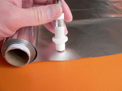
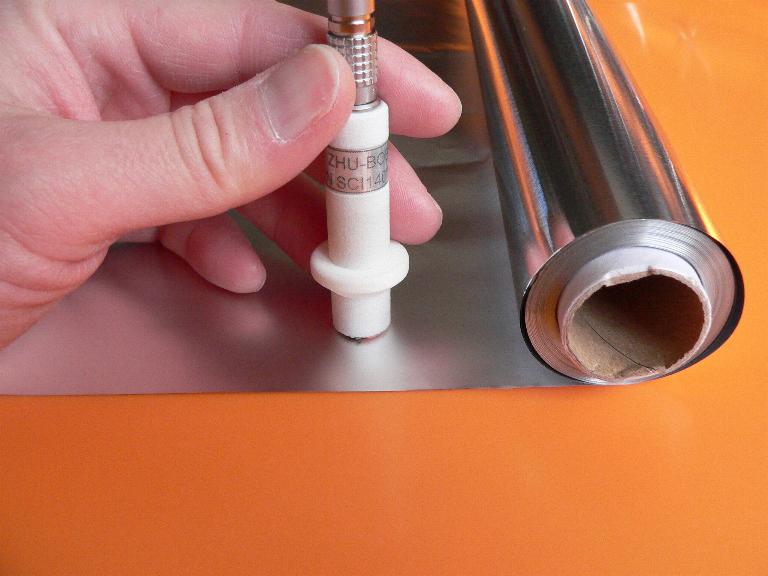
In this experiment, we try to measure the thickness of a thin aluminum sheet. After manufacturer's specifications, the nominal thickness value is 12 µm.
This value can also be determined with precision by a simple caliper: we take a measurement of a stack of 10 sheets and obtain a total thickness of 120 µm. This value can be measured by a caliper. By dividing the obtained value by 10, we get a averaged value of 12 µm. Since the measurement error was also divided by 10, this method is reliable enough.
We can see how eddy current can make the same measurement more quickly. However, we need to determine the electrical conductivity of the aluminum first, because the thickness is too small so simultaneous measurement of conductivity and thickness is not possible.
The electrical conductivity of the aluminum sheet is not indicated by the manufacturer. We can determine it by a resistance measurement. To do this, we cut a strip of 10 mm large and 297 mm length from the sheet. We take a measurement the resistance
of the strip using an impedance meter. The measured resistance is equal to 0.075 ohm. It can be expressed as function of strip section and strip length as follow:
where
is the resistivity of aluminum,
the strip section and l, the strip length. So:
(ohm*meter)
the electrical conductivity
is the inverse of the resistivity
:
(S/m), or nearly 33 MS/m
Once the electrical conductivity determined, we can enter it as a parameter to the measurement software.
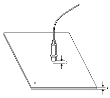
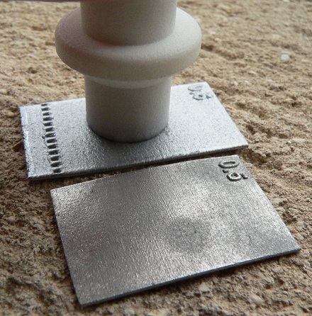
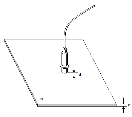
Now, let measure the sheet thickness by eddy current method. To do this, apply a probe on the sheet. Note that there is no electrical contact between the probe and the sheet. We can even insert some paper sheets between them. In order to check the lift-off range, we can insert several spacers of 0,1 mm thickness each.
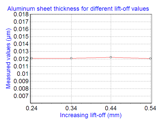
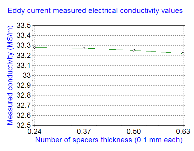
A multifrequency measurement in the range between 50 kHz et 800 kHz gives, for different values of lift-off, the estimated thickness values below (the curve on the left).
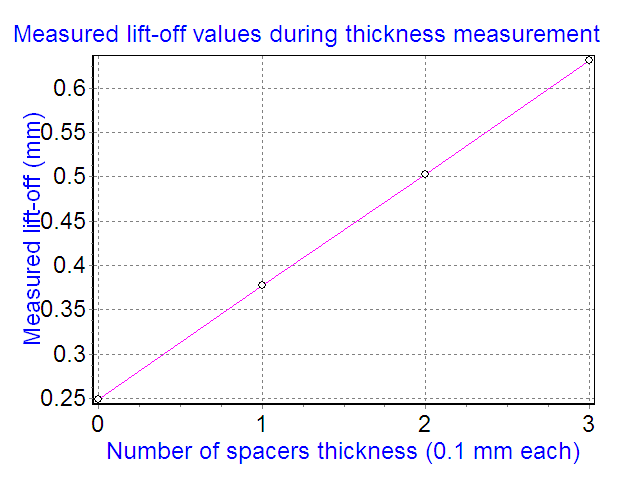
The system measures at the same time the lift-off value which is plotted in the curve on the right.
Note : the eddy current measurement is much faster than a measurement by caliper. It is also more precise and stable because dust and folding have no effect on the measurement.
Utilized measurement system: Conducsenstm/TK-Senstm
Thickness measurement: values measured by eddy current method are very close to that given by the manufacturer, in despite of augmentation of the lift-off
Lift-off measurement: very good linearity!
We can note the the initial lift-off which is due
to the probe manufacturing is about 0.25 mm.Measurement of thickness of tubes (inconel, titanium, copper, aluminum) return home
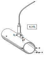
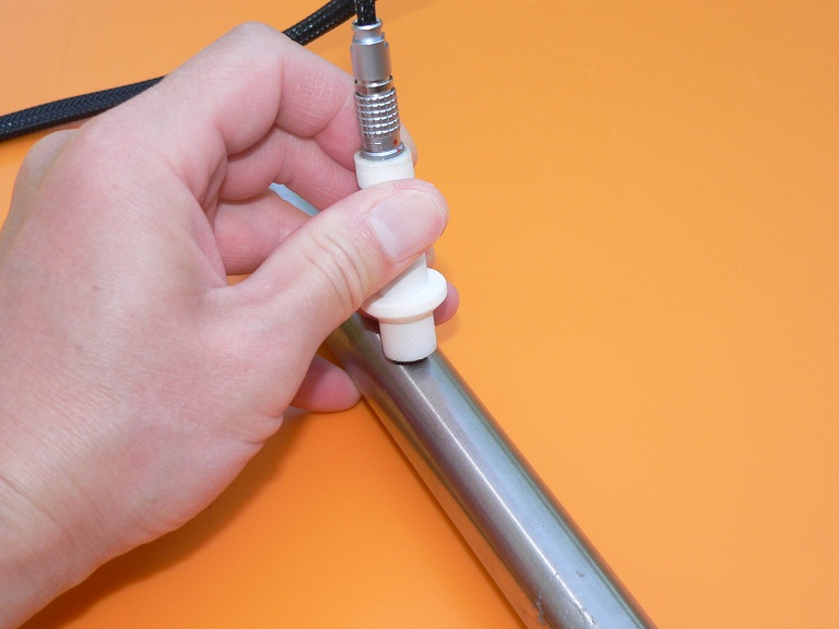
On site inspection requires thickness measurement from the outside of the tubes at one or more points on the tube circumference.
The calibration can be made on available standards but can tolerate materials differences, as the tube material is not always exactly the same as that of the standards.
Lift-off, tilt and lateral deviation of the probe are also well supported.
Utilized measurement system: Conducsenstm/TK-Senstm
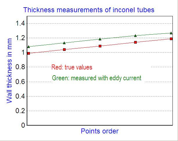
Above: eddy current thickness measurement results (green)
versus true values (red).
Note that the eddy current measurement was carried out without any prior calibration. Systematical error is constant in all the measurement range and can be easily removed with a one-point calibration measurement.Eddy current measurement of steam generator tube thickness in laboratory
Online measurement of aluminum sheet in rolling plant return home
The thickness of the sheet being rolled is continuously measured. The reading is used to perform a continuous adjustment of the system to achieve optimal regularity.
The accuracy in the thickness of the laminate also allows a substantial saving in raw material.
The probe is placed above the sheet being rolled at a safe distance in order to not deteriorate its surface. The process can tolerate large lift-off and tilt angles variation.
Because there can be differences in electrical conductivity of the utilized alloys, the system can measure it and make the measured thickness alloys-independent.
The probe is installed above the sheet to be measured at a safe distance
Online inspection at Péchiney
Online measurement of aluminum tubes bottom return home
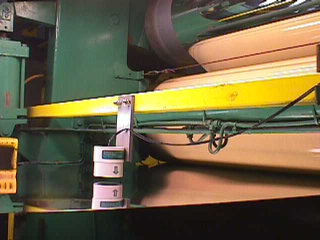
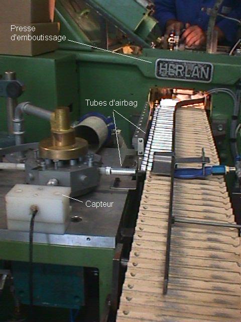
The bottom of an airbag detonator tube is a critical area. Its thickness determines the instant when the tube explodes and triggers the inflation of the airbag. It is important to measure the bottom thickness one by one. Because of the great quantity of manufactured tubes, the measurement can take a lot of time.
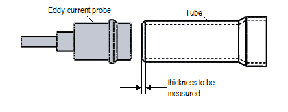
Eddy current measurement provides a quick mean for the thickness checking process: the measurement is performed from only one side of the tube and needs no mechanical contact.
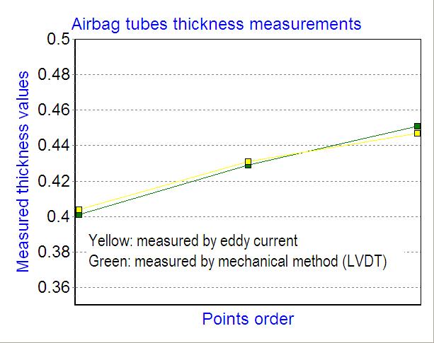
However, when the aluminum alloys have variations in electrical conductivity, the estimated thickness is affected and may be erronous. This difficulty can be overcome by measuring the conductivity at the same time as the thickness. The measured conductivity value will be used to correct the measured thickness. This enables alloy-free thickness measurement.
Eddy current measurement of aluminum tube bottom thickness
Application example
1. Nominal thickness value
0,425 mm
2. Precision
typically 10 microns (0,01 mm) can attain 3 microns
3. Measurement speed
0,7 s per tube
4. Allowed lift-off range
0,5 mm
Industrial application: tubes measured at the output of a
horizontal aluminium cold impact extrusion press
Measurement of distance and objects detection return home ![]() Top of page
Top of page![]()
Multifrequency distance measurement return home
In order to measure the distance between a probe and a target, we utilize the multifrequency technique to eliminate the effect of target material.
It is well-known that the eddy current signal depends strongly on the target material. When the target material is not constant and changes from one piece to another, this variation may be interpreted as a distance variation. A measurement error will occur.
The multifrequency method allows to suppress the effect of material changes from the distance measurement, thus improving the precision.
Vibration measurement return home
When a target vibrates, the target-probe distance varies. So, the distance measurement can reproduce the vibration. This is a non contact measurement which is more advantageous than other methods because it does not modify the mechanical behaviour of the vibrating system.
Some vibrations are at very low frequencies such that the ear can not detect them. Unlike acceleration sensors, the eddy current method is very sensitive at low frequencies.
Even at higher frequencies, the eddy current sensor can capture faithfully a sound. Click on this link to discover the "music" captured by an eddy current sensor.
Multisensors technique for detection in complex environment return home ![]() Top of page
Top of page![]()
Sometimes, we may focalize attention on an object in a complex system and want to measure its position. However, when other objects move during the measurement, the measured position can be disturbed if this position is measured by only one sensor. The solution is to use several sensors that capture the global signals of the system. Then a multiparameters signals processing will be applied to the set of signals in order to retrieve the wanted position and discard the unwanted signals.
Measurement of electrical conductivity return home ![]() Top
of page
Top
of page![]()
Non contact eddy current conductivity measurement of a conductive sheet
Non contact electrical conductivity measurement of solid materials
Electrical conductivity is a very important parameter which characterizes a product. For example:
Eddy current technique allows to measure the conductivity of a material without any electrical contacts with it. The measurement can even be made through the packaging or paint layers, so preserves the surface of the measured product. Non contact measurement enhances also higher speed testing.
Advantages of the Sciensoria's eddy current conductivity measurement technique:
These features extend considerably the application field of eddy current conductivity measurement.
Conditions for simultaneous measurement of conductivity and thickness
The Conducsens(tm) system excites the target with frequencies in the range [fmin-fmax] which correspond to the penetration depth [dmax-dmin]. The thickness t will determine the condition for simultaneous measurement of thickness and conductivity:
Electrical conductivity measurement of thin sheets return home
In a previous example, we shown how to measure the thickness of a thin aluminum sheet (12 µm thick). The electrical conductivity of the sheet was measured with a 4-contacts method and evaluated at 33 003 300 S/m (33 MS/m).
Instead of measuring the sheet thickness, we can measure its electrical conductivity by the eddy current method.
To do this, we have to enter the 12µm value as an input parameter because for this thickness value it is not possible to measure both parameters simultaneously (see conditions on thickness above).
The measurements were made at several lift-off values in order to test the robustness in regard of the lift-off variations.
The measurement results are shown below.
Conductivity measurement result with increasing lift-off
Matching between measured data ans model data on 10 exciting frequencies
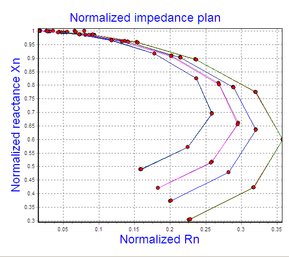
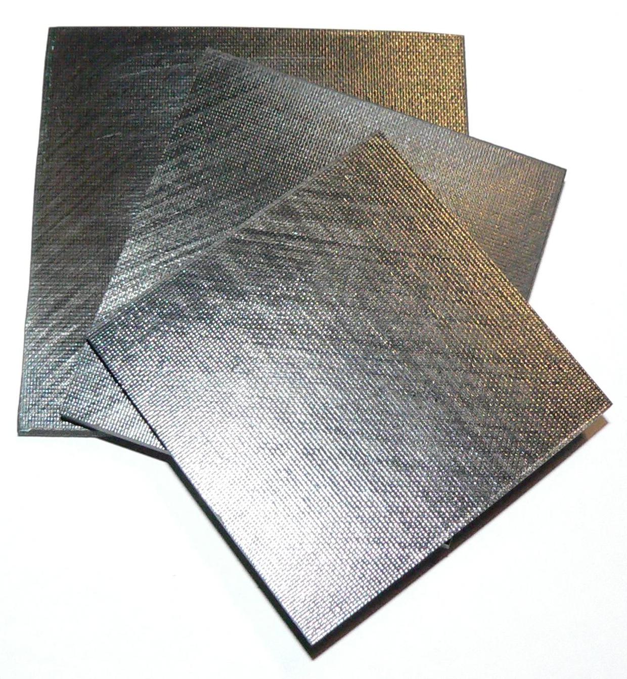
Electrical conductivity measurement of carbon composite (CFRP) return home
A carbon composite material is composed of carbon fibers and epoxy resin. The fibers have not always electrical contacts between them, so make conductivity measurement by the 4-contacts method is not possible. The eddy current method is a good solution to the problem because it allows to create current inside the fibers without touching them.
The measurement time is infinitely shorter than that of a contacts method: a measurement only takes several seconds.
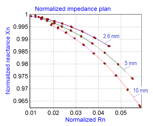
The three samples shown were made with a same process but have different thicknesses: 2.6 mm, 5 mm et 10 mm. The aim of the experiment is to measure their conductivity values without to be affected by their differences in thickness.
CONDUCSENS™ gives:
- For the 5 mm thick plate, the estimated conductivity is 14 685 S/m
- For the 10 mm thick plate, the estimated conductivity is 14 810 S/m
The curves on the right side show excellent matching between experimental data and computed data (in reality, there are 6 curves: 3 measured and 3 computed ones). It is worth to note that each plate corresponds to a different curve, but the estimated conductivities are very close each to other. This is quite credible because the 3 plates were made with a same process.
Comment: if the thicknesses of the 3 plates were considered to be equal to 2.6 mmm, the corresponding estimated conductivities are:
- 25 414 S/m
- 38 305 S/m
Obviously, the last 2 values are false. The thickness should have been taken into account to avoid these errors.
Blue curve: measurement result with plate thickness taken into account
Red curve: measurement result with plate thickness considered to be equal to 2,6 mmElectrical conductivity measurement of ferrous metals return home
Applications of ferrous metals conductivity measurement
- Thickness measurement: in many cases, the wall thickness of a tank or pipeline is to great to be measured by an eddy current process. However, one can use eddy current method for measuring the electrical conductivity of the metal and a 4-contact method for measuring the resistance of a section of the wall. Once conductivity is known, thickness can be deduced from the resistance of the wall.
- Magnetic circuit design and manufacturing: in electrical machines or actuators, many pieces of the magnetic circuit are made from mild steels (for example: XC10).
- In design step, it may be necessary to determine the electrical conductivity of the metal in order to feed the result to a finite-elements design software.
- In manufacturing step, it may be necessary to measure the raw material destined to the manufacturing in order to make sure that it meets the quality requirement.
The video below shows how to measure the electrical conductivity of a electrical actuator by eddy current method
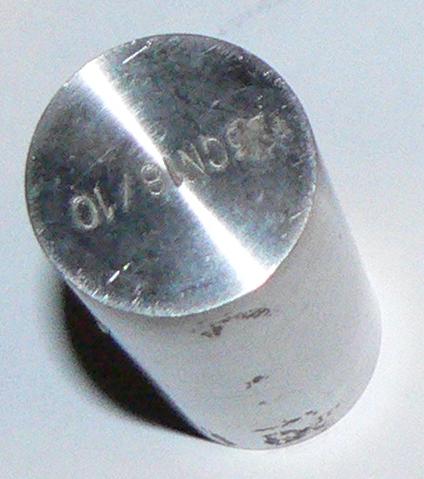
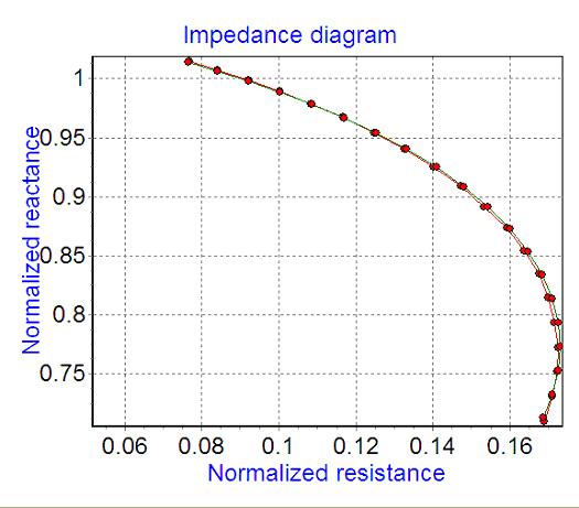
Conductivity of a magnetic stainless steel (z3cn18/10)
The reference of the metal is z3cn18/10. Impedance measurements indicate that the metal is magnetic (air-impedance is smaller than target-impedance). Consequently, the permeability search option has been activated within the Conducsens™ software during the conductivity measurement.
Conducsens™ indicates:
The figure on the right side shows how measured data match computed data. The data was collected from a frequency sweeping over 20 points.
Electrical conductivity of cast iron
Article about the measurement of the electrical conductivity of ferrous metals (pdf)
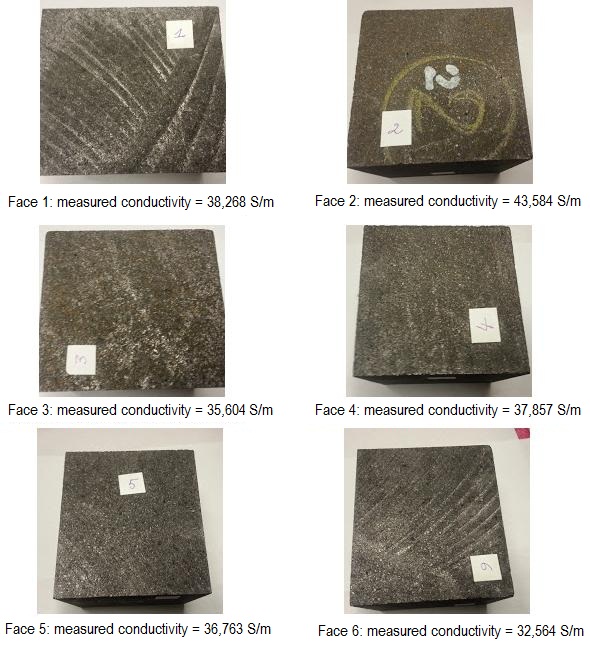
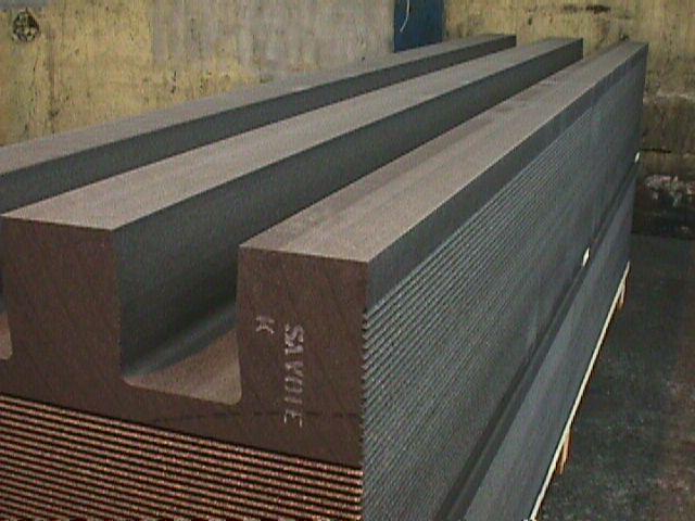
Electrical conductivity measurement of graphite return home
Graphite electrode under test (UCAR La Léchčre)
Comment: only the eddy current method can measure the electrical conductivity on the 6 faces of a cube, not the 4-points method.
Measurement of electric conductivity on the 6 faces of a graphite cube
Sorting of contacts destined to electrical contactors return home
The tip of a contact used in a contactor have 2 different faces: one is specially treated in order to support electric arcs, the other, covered by a brazing layer, is destined to be bonded to a support in the contactor electric circuit.
If the two faces were interverted during the soldering, the contactor will go rapidly out of service.
An eddy current probe can rapidly determine the good face of the tip to be bonded, thus eliminates the risk of confusion.
Alliages sorting return home
This video http://www.sciensoria.fr/zscope_zplan.wmv shows a demonstration of metals sorting by an eddy current encircling probe and a
Z-Scope.
Detection of flaws
return home ![]() Top of page
Top of page![]()
Detection of flaws on steam generator tubes
Tube characteristics:
The flaws are simulated by EDM notches with the following characteristics:
In general, the external circumferential flaws are the most difficult to detect.
The used probe is a high definition, self-nulling rotative probe. It features the "analyzing current sheet generating" possibility.
One can see that all the EDM notches down to 20% wall thickness-depth are easily detected. The 10% one was detected with some simple additional signal processing.
The powerful software Eddysens(tm) allows to represent the captured signal in cartography mode, color and contour modes. A region of interest can be defined and submitted to various treatment operation. Below, a simple threshold rescaling allowed to see smaller notches signals.
Output signals of a high resolution self-nulling probe: detection of external circumferential EDM notches with depth as small as 10% of tube wall thicknesss